DIY Crystal Set Radio Instructions
| Return to SatCure Hobby index page I remember the excitement of building my first crystal set at age ten!
But, whether you are 10, 100 or somewhere in between, you'll experience great delight in building this little radio from the most basic components.
I looked at many designs before deciding on this one. Some had enormous coils of wire and some used expensive parts. This one has neither. It uses the most basic component parts but gives good performance and needs NO batteries. NO SOLDERING is required.
There are various designs which avoid using an expensive tuning capacitor. Everything from paper clips scraping across bare wire coils to ferrite rods used for tuning. I didn't like those designs but I couldn't afford to pay ten pounds ($15) JUST for a tuning capacitor! I wanted to make the complete kit for less than that!
Visit http://www.midnightscience.com/ (crystal set society) | 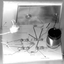
|
The solution, as with many things, was simplicity. A capacitor is, basically, just a couple of metal plates held apart by an insulator. Move those plates and you vary the capacitance. My final design uses the front panel with aluminium foil glued to it as one plate. The insulating layer is the paper plan itself which you cut out and glue on the foil. The final part is a thin metal plate which is held to the front panel with a single screw. You rely on its own inherent springiness to move the plate away and a simple one-inch bolt to bring it back.
Made this way, the design is simple and low-cost but you must take great care to avoid tearing the flimsy foil or the paper. Also, don't let the paper become damp!
Shopping list:
| 1 metal plate 102 x 63 x 0.4mm (HZ93B or HZ96E from Maplin)
(Hint. You could cut a piece out of a steel oil can or similar)
Tinned copper wire
1 Aluminium foil 100 x 80mm (as used for wrapping food)
1 reel 30swg enamelled copper wire 70m in length (BL40T from Maplin)
1 crystal ear piece (LB25C from Maplin)
1 in-line earpiece socket to suit ear piece plug. Solder 2 wires to the socket.
2 100 x 140 x 6.3mm MDF or other soft wood 1/4" thick for front panel. Base may be thicker.
1 disc capacitor 10nF (= 0.01uF)
1 39k resistor (with coloured stripes orange-white-orange)
| 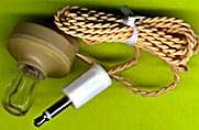
Crystal earpiece |
| 1 germanium diode (OA81, OA91, OA90, OA47, 1N34 or similar) |  |
| 1 knob with 6.3mm hole
1 bolt M6 x 25mm (1 inch) or longer
1 nut M6 to be glued into front panel or use a "Tee nut" which has hammer-in spikes.
12 Short screws 6mm long No.8 x 3/8" "plastite"
1 Photographic film roll container, plastic 30mm dia x 50mm
2 screws, front panel fixing No.6 x 3/4"
1 insulated stranded wire 5 metres long
|  Tee nut + bolt |
You will need the following tools:
Small pair of sharp, pointed scissors for cutting paper and foil.
Small, sharp knife for cutting foil.
Cross-head screwdriver.
Drill bits: 3.0mm, 6.3mm (1/4"), 9.5mm (3/8")
Small screwdriver with 3mm flat blade.
Fine sandpaper, emery board or similar abrasive material.
(Hint: you might have all of these on a Swiss army knife)
Glue for sticking paper to wood. Preferably one of those like lipstick.
A pencil.
If you intend to use the radio outside a building:
You will also need a copper tube for grounding.
This may be tube or rod, about 13mm diameter and at least 600mm long - preferably more.
A tree, pole or balloon will be required to get the antenna wire as high as possible.
Construction
Winding the coil is a pain! Believe me, I've wound plenty. Mostly on smelly old toilet paper roll centres. These tend to be flimsy so I can't post them. Also, I just don't go to the bathroom that often. That means you would have to find one. Well, I wanted this kit to be complete in every way. If you are building this radio in a scout camp in the middle of a field, there's going to be an awful rush for the one bathroom when everyone reaches the line that says "now take a cardboard toilet roll and..."
So I found a really low cost solution which simplifies the coil winding process:
What do photographic shops do with the little plastic holders that you put your film roll in before developing?
Wrong! They give them all to me. Those little plastic containers are ideal for coils. They just happen to be the right size and it's easy to make holes and slots in them. Better still, the thin coil wire glides smoothly across the plastic surface, making it much simpler to wind a coil than if you used a cardboard tube. Cool.
Fixing the finished coil in place is easier, too. Just put a screw through the closed end of the plastic container.
(Try to do that with a cardboard tube!)
The instructions may look a bit frightening but just take them one at a time and tick each one on this page with a pencil as you complete the operation. ("tick" in English means "check" in American).
Let's make the coil first:
01. Make a small hole in the bottom of the plastic container for the securing screw.
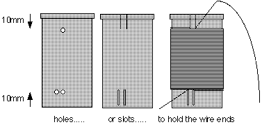
02. Take the plastic container and make two tiny holes in it 10mm from the closed end and 5mm apart.
(Hint. You could use a hot needle or the point of the scissors or knife. Slots will also work just fine.)
03. Make another tiny hole 10mm from the open end, or cut two slits. The actual position is unimportant.
04. Make a hole in the centre of the base of the container for the fixing screw.
05. Take the reel of thin copper wire and remove insulating varnish from the end using the sandpaper.
06. Thread the wire into the hole or slot nearest the base and out of the adjacent one.
07. Leave approximately 30mm of wire sticking out of the plastic container.
08. Now wind 65 turns of wire around the container. Keep pushing the turns together as you add them.
(There should be no gaps or overlapping.)
09. After 65 turns, cut the wire to leave approximately 80mm of wire and push it through the top hole or slit, around the lip and through the hole, again, to secure it.
10. Use sandpaper or a knife blade to remove the varnish from the ends of the wire.
11. The turns of wire may be secured with tape or glue if necessary to keep them together.
Now prepare the base:
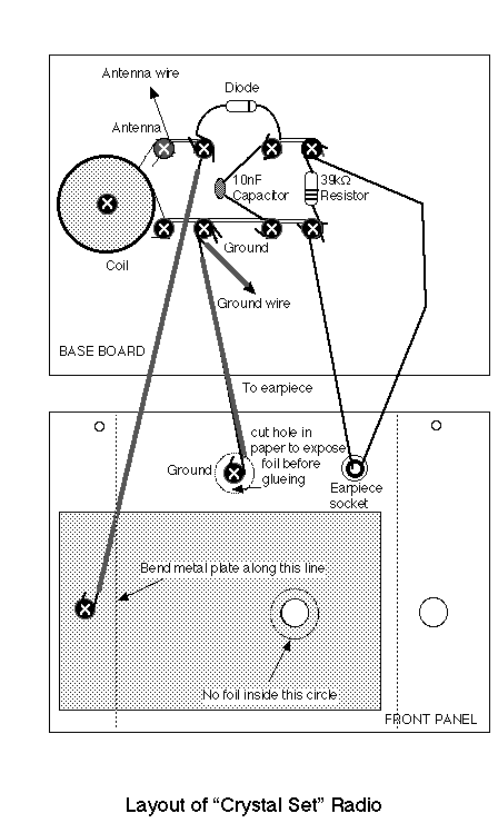
12. Cut the base panel component layout out of the paper sheet, following the rectangular outline as a guide. (Print out the "gif" images from the bottom of this page).
13. Spread glue across the top of the base panel and fix the paper to it.
14. When the glue has dried, drill the screw holes with a 3.0mm drill.
Now the front panel and tuning capacitor:
15. Spread glue across the rear of the front panel and fix the aluminium foil to it.
16. Leave a strip clear at the end with the small hole as shown in the sketch.
17. Smooth the foil down before the glue dries and trim any excess foil around the edges of the panel.
(Take care since the foil tears easily!)
18. Use a sharp knife to cut away a circle of foil around the larger hole, as indicated in the sketch.
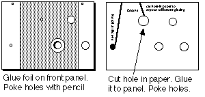
19. Cut the front panel sketch out of the sheet, following the rectangular outline as a guide.
20. Cut a circular piece out of the paper for the ground screw.
21. Spread glue across the entire rear of the front panel and foil and smooth the paper onto it.
22. When the glue is dry, drill all front panel holes with a 3.0mm drill. Then enlargen the most central hole to 6.3mm (1/4") for the large tuning capacitor screw. Rebate the hole at the front of the panel and glue the nut in place with quick-setting epoxy. Enlargen the right hand hole for the volume control if the amplifier kit is to be added. Enlargen the hole for the ear piece socket to make it a tight press fit.
Leave the remaining screw holes at 3.0mm.
Do some more with the base:
23. Use eight short screws to fix the wires to the base panel.
(Follow the sketch which you glued to the base panel).
24. Fit the resistor, capacitor and diode. Be sure to wrap the wires clockwise around the screws.
25. Take the insulated wire and cut two pieces, one 600mm long and one 100mm.
26. Strip 10mm of insulation off each wire and twist them together.
27. Connect them to the ground point on the base panel.
28. Connect the short wire to the front panel ground point.
Back to the front panel, if the glue is dry:
29. Fix the metal plate to the front panel with a short screw.
30. Bend the plate near the screw until the end farthest from the screw remains approximately 20mm away from the panel.
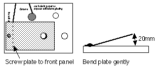
31. Thread the large bolt through the metal plate into the front panel nut.
32. Screw the bolt through the panel and fit the knob, tightening its grub screw to secure it.
33. Fit a short screw into the ground hole in the front panel. The aluminium foil should be visible here.
34. Feed the wires of the ear piece socket through the hole and press the socket into the panel.
35. Screw the front panel to the base panel, using the two longer screws.
Finishing off:
36. Screw the coil to the base and connect its wires to the appropriate screws.
37. Connect the ear piece socket wires to the screws.
38. Connect the 600mm wire to a suitable ground point such as a cold water pipe or a long rod hammered into damp soil. Extend the wire, if necessary, by twisting its bare end to the end of a longer piece.
39. Using sandpaper, remove 10mm of varnish from the end of the thin wire on the reel.
40. Connect this end to the antenna screw on the base board.
41. The reel of thin wire should be unwound and the end raised as high as possible off the ground but read the safety precautions first!
SAFETY FIRST
DO NOT use an electric wall socket or connect to any electrical appliance to ground your radio.
Use a cold water tap or a ground rod hammered into damp soil (dry soil is better than nothing!)
Do not mount your antenna wire over or near to electrical power lines or telephone lines or ANY kind of lines!
The antenna wire could easily break or move and touch the power lines. You could suffer severe ELECTRICAL SHOCK or even DIE.
DO NOT leave your antenna connected to the radio when not in use. Connect it to the ground wire, preferably outside. DO NOT use your radio at all if there's an electrical storm anywhere near.
The ear piece tube unscrews. It's a good idea to wash it often so you don't pass around an ear infection.
Don't get water inside the ear piece. The corner shop doesn't sell them.
Using Your Crystal Set Radio
The radio will run on just the power collected by the antenna. That's not very much so don't expect the sound to blow your head off. You'll hear some stations clearly if everyone keeps quiet. It certainly won't annoy the neighbours!
You'll probably hear three or four stations as you turn the tuning screw. There's more change in capacitance in the first turn than in the next twenty as the capacitor plate moves away from the panel.
A crystal set radio has "poor selectivity." This means that stations tend to overlap and blot each other out. This is worse at night and worse with a long, high antenna. However, if the antenna is too low or too short, you'll hear very little! It's all a matter of compromise. Experiment with the antenna position and length.
Try wrapping a few turns of the ground wire around the coil. Notice anything? Better or worse?
Now wrap a few turns of the antenna wire around the coil instead. Now wrap it the opposite way.
What happens if you disconnect the ground wire?
Will your bed frame work as an antenna or a ground?
How does it work?
The long wire antenna captures radio signals which are broadcast around the country.
Each programme signal consists of a fixed high frequency "carrier" which is "modulated" by the programme sound.
Most of the radio signals are fed away to ground via the coil and capacitor but programmes at the tuned frequency are passed to the diode instead.
The diode circuit rectifies the signal, effectively extracting the programme sound from the high frequency carrier.
The actual carrier frequency which gets through to the diode is determined by the tuning circuit which consists of the coil and capacitor. If you alter either the inductance of the coil (change the number of turns or the physical dimensions) or the capacitance of the capacitor (change the size of the plates or move them closer or apart) then you alter the tuned frequency.
Amplifier for Crystal Set Radio
Now that you have built your radio successfully, you might want to make it louder.
The following parts will enable you to do just that. The instruction numbers follow on from previous sheets.
The following parts are required:
| Tinned copper wire
1 100k resistor (with coloured bands brown-black-yellow)
1 electrolytic capacitor (1uF any voltage rating)
1 NPN transistor BC547, 2N3709, BC238 or similar
1 10k log volume control potentiometer with nut
1 knob to fit volume control spindle
1 battery cell 1.5 volts
1 battery holder
7 screws 6mm long No.8 x 3/8" "plastite" |  Volume control potentiometer Volume control potentiometer |
Construction
42. Dismantle the components and screws attached to the base.
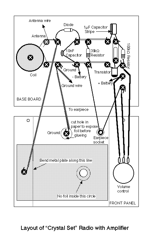
43. Glue the new base layout sketch to the base and drill the extra holes with the 3.0mm drill.
44. Fit the wires, screws and components according to the sketch.
45. Fix the volume control to the front panel with its nut and fit the knob.
46. connect the capacitor and resistor. Note that the capacitor must be fitted with stripe to the left.
47. Connect the volume control and earpiece.
48. Fit the transistor (carefully, without snapping the short wires).
49. Connect the battery holder. The spring should be connected to a ground screw.
50. Check the connections and make sure that the flat side of the transistor is uppermost.
51. Make sure that the transistor legs are not touching adjacent screws.
52. Put the battery cell into the battery holder with its flat end to the spring.
(Alternatively, the amplifier can be powered from a higher voltage
battery up to 9 volts or from a solar cell).
How does it work?
The capacitor connects the sound to the transistor without allowing the battery voltage to go back into the crystal set. The 100k resistor feeds a small current from the battery into the input ("base connection") of the transistor. This current turns the transistor partially "on" and allows current to flow from the battery through the transistor and volume control (another resistor). The sound passing into the base connection of the transistor makes the current through the volume control change and the transistor uses the battery power to amplify this change so the sound is louder. The centre tag of the volume control is connected to the rotary spindle and "taps off" just as much of the sound as you want to hear.
Questions:
Is the sound louder than without the amplifier?
Is the tone different?
Can you hear more stations?
Do the stations overlap each other?
Will the radio now work without a ground connection?
Will it work without an antenna connection?
Will it work if you disconnect the antenna wire and place your finger on the antenna screw?
What can you hear without the battery fitted?
Notes:
You can still use the crystal set radio if the battery dies. Simply disconnect the 1uF capacitor from the diode and connect the ear piece wire instead, just as it was connected before you built the amplifier.
Print out these sketches:-
Return to SatCure Hobby index page


 Volume control potentiometer
